Garrett
Chip Installation Page 7.6.1 Typical 1.8T ECU. Chip is a 44-pin PSOP.
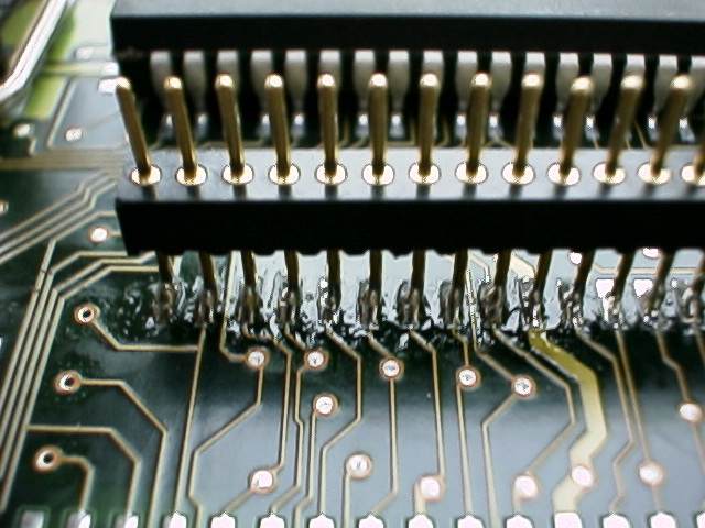
Step 1: De-solder this chip. It is best to use specialized Surface Mount (SMD) de-soldering equipment, but it can be done with a temperature-controlled soldering iron with a very fine tip. If using a soldering iron, heat and lift one pin at a time. Step 2: Remove any excess solder on the circuit board using "solder wick" (copper braid). Step 3: Garrett Encryptor Module is supplied with two sets of pins. Insert the pins in the socket in the bottom of the encryptor module. Step 4: Carefully position the Encryptor Module so that the pins line up with the pads on circuit board. Solder 2 end pins on each row to the board. This will hold the pins in place Step 5: Remove Encryptor module from pins by pulling straight up. This will allow easier access to the rest of the pins. Solder all remaining pins to the board. The results should look like this:
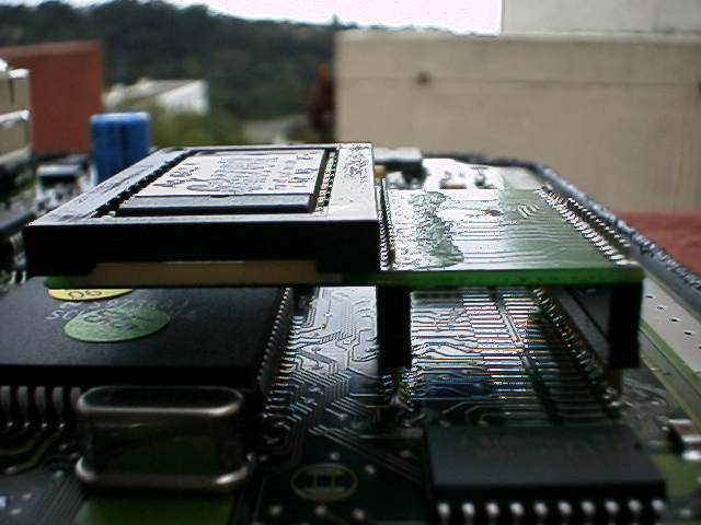
Step 6: Carefully inspect all 44 pins using a magnifying glass to ensure that all are properly soldered and no solder has splashed or flowed someplace where it could cause a short circuit. Step 7: Re-install encryptor module on Pins, like this:
Step 8: IMPORTANT: See next page
|


